

Air Circuit Breakers (ACBs) are high-capacity, low-voltage electrical switching devices designed to protect, control, and isolate heavy-duty power distribution systems. Operating at voltages up to 1,000V AC and typically handling currents from 800A to 10,000A, they are the industrial workhorse for safeguarding critical infrastructure against overloads, short circuits, and electrical faults. Unlike miniature breakers (MCBs) or molded-case breakers (MCCBs), ACBs use air as the primary arc-quenching medium, offering exceptional durability, high breaking capacity, and advanced protection features for large-scale commercial, industrial, and utility applications.
An Air Circuit Breaker (ACB) is an automatically controlled mechanical switch that:
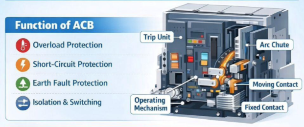
● Protects: Detects overloads, short circuits, earth faults, and abnormal conditions, then rapidly trips (opens) to interrupt current and prevent equipment damage, fires, or hazards.
● Controls: Manually or remotely switches circuits on/off for normal operation, maintenance, or system reconfiguration.
● Isolates: Provides a visible, secure break in the circuit for safe maintenance and personnel protection.
● Monitors: Modern ACBs integrate smart trip units for real-time current/voltage/power monitoring, fault diagnostics, and communication.
ACBs are categorized by arc-quenching design, construction, and application:
1. Plain Break (Cross-Blast) ACBs
o Simplest design: Contacts separate in open air; arc is cooled/split by natural air flow.
o Use Case: Low-voltage (≤1kV), low-current applications; cost-effective for small systems.
2. Magnetic Blowout ACBs
o Uses series-connected blowout coils that generate magnetic fields to push arcs into arc chutes.
o Advantage: Current-adaptive arc control—higher fault currents = stronger magnetic force = faster quenching.
3. Arc Chute (Splitter Plate) ACBs
o Most common modern design: Arc is forced into a chamber with metal splitter plates, which cool, split, and extinguish the arc.
o Use Case: Standard industrial, data center, and utility applications.
4. Air Blast ACBs
o Uses compressed high-pressure air to blow out arcs; historically for high-voltage systems.
o Note: Rare in modern low-voltage ACBs due to complexity.
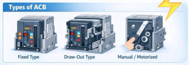
1. Fixed Type ACBs
o Permanently mounted; direct busbar connection; lower cost.
o Use Case: Static systems with minimal maintenance needs.
2. Drawer-Type (Withdrawable) ACBs
o Modular design with 3 safety positions:
o Connected: Normal operation (main/auxiliary circuits active).
o Test: Main circuits isolated; auxiliary circuits powered for safe testing.
o Separated: Full electrical isolation for maintenance/repair.
o Advantage: Fast replacement, no shutdown of entire panel.
● 3-Pole (3P): For 3-phase systems (most common).
● 4-Pole (4P): 3 phases + neutral; for systems requiring neutral isolation (e.g., TN-S, TT earthing).
ACB performance is governed by IEC 60947-2 (2024), the global standard for low-voltage circuit breakersIEC Webstore:
| Parameter | Description | Typical Values |
| Rated Voltage (Ue) | Normal operating voltage | 400V, 415V, 690V AC |
| Rated Current (In) | Continuous carrying current | 800A–10,000A |
| Rated Short-Circuit Breaking Capacity (Icu) | Max fault current interrupted safely | 50kA–150kA @ 415V |
| Rated Service Short-Circuit Breaking Capacity (Ics) | Icu percentage (reusable after trip) | 75%–100% of Icu |
| Rated Short-Time Withstand Current (Icw) | Current carried without damage (time-rated) | 30kA–85kA for 1s/3s |
| Operating Temperature | Safe ambient range | Standard: -5°C to +40°C; Wide: -25°C to +70°C |
| Protection Class (IP) | Enclosure protection | IP20 (indoor), IP40, IP54 |
| Mechanical Endurance | Operating cycles | 10,000–30,000 cycles |
| Electrical Endurance | Fault-interruption cycles | 1,000–5,000 cycles |
● Industrial Plants: Main incomers, motor control centers (MCCs), transformer/generator protection.
● Data Centers: UPS systems, bus couplers, critical load distribution.
● Commercial Buildings: High-rise power distribution, HVAC, and backup generators.
● Utilities & Infrastructure: Substations, distribution panels, railway electrification.
● Marine & Offshore: Shipboard power systems (marine-certified ACBs).
● Renewable Energy: Solar/wind farm grid connection, inverter protection.
● Rated Current (In): ≥ maximum continuous load current (1.1–1.2x safety factor).
● Short-Circuit Capacity: Icu ≥ calculated system fault current (I"k3).
● Poles: 3P (standard) or 4P (neutral isolation required).
●Trip Unit Type:
o Thermal-Magnetic: Basic overload/short-circuit protection.
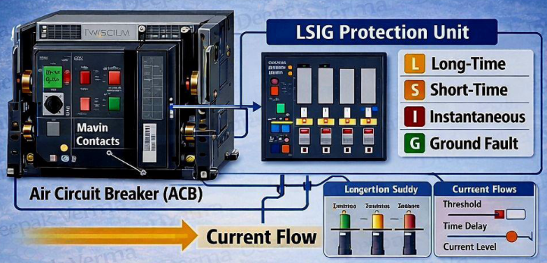
o Electronic (LSIG): Advanced (L=overload, S=short-delay, I=instantaneous, G=earth fault).
o Smart (LSIGM): Communication (Modbus, Profibus), remote control, data logging.
● Operating Mechanism: Manual (hand-charged) or motorized (auto-charged/remote).
● Ambient Temperature/Altitude: Derate for >2,000m altitude.
● Standards: IEC 60947-2, IEC 60947-1, GB 14048.2 (China), UL 489 (North America).
● Certifications: CE, IEC, CSA, marine (DNV, ABS) for offshore.
● Selectivity: Ensure upstream/downstream breaker coordination (Class A/B per IEC).
● Interlocking: Key interlock, zone selective interlocking (ZSI) for multi-breaker systems.
Core Components
1. Frame/Chassis: Steel/aluminum alloy (structural support).
2. Contact System:
o Fixed/Moving Contacts: Copper alloy (Cu-Cr, Cu-W) + silver/tin coatings (low resistance, anti-weld).
o Arcing Contacts: Tungsten-copper (high arc resistance).
3. Arc Chute: Steel splitter plates, insulating barriers (Bakelite, DMC).
4. Operating Mechanism: Spring-charged (energy storage), toggle linkage, trip latches.
5. Trip Unit: Electronic (microcontroller, sensors) or thermal-magnetic (bimetal, solenoid).
6. Auxiliaries: Undervoltage release (UVR), shunt trip (ST), auxiliary switches (AX), alarm contacts.
● Conductors: High-conductivity electrolytic copper, silver alloys.
● Insulators: DMC (Dough Molding Compound), BMC, epoxy resin, heat-resistant plastics.
● Metals: Cold-rolled steel (frame), stainless steel (hardware), aluminum (heat sinks).
● Arc-Resistant Materials: Tungsten, ceramics, refractory metals.
● Stamping/Punching: Steel frame/parts from precision dies.
● Machining: CNC machining of contacts, shafts, and mechanical parts.
● Molding: Insulating components (DMC/BMC) via compression molding.
● Assembly: Sub-assembly of mechanisms, arc chutes, and trip units.
● Chassis, contact system, arc chute, and mechanism integration.
● Wiring of control circuits and auxiliary components.
● Drawer-type unit testing (connected/test/separated positions).
1. Visual Inspection: Dimensional accuracy, finish, labeling.
2. Contact Resistance Test: Milliohm measurement (≤50–100μΩ per pole).
3. Dielectric Voltage Withstand Test: Hi-pot test (2.5–3.5kV AC for 1min).
4. Operating Mechanism Test: 50+ on/off cycles; smooth operation.
5. Trip Unit Calibration: Overload/short-circuit/earth-fault threshold verification.
6. Temperature Rise Test: Under rated In; max temperature rise ≤60K (IEC).
7. Auxiliary Function Test: UVR, shunt trip, interlock validation.
8. IP Protection Test: Dust/water ingress (per rated IP).
· Anti-corrosion treatment, sealing, and wooden crate packaging.
· Test report, manual, and certificate of compliance (CoC) included.
Type tests validate design compliance with IEC 60947-2 (performed on prototype samples):
1. Short-Circuit Making/Breaking Tests: Verify Icu/Ics/Icm under fault conditions.
2. Short-Time Withstand Test: Validate Icw for 1s/3s without damage.
3. Mechanical & Electrical Endurance Tests: Cycle testing to rated life.
4. Temperature Rise Test: Full-load thermal performance.
5. Dielectric Test: Power frequency and impulse voltage withstand.
6. Trip Characteristic Test: Accuracy of protection curves.
7. Environmental Tests: Vibration, shock, temperature/humidity cycling.
8. Arc-Fault Containment Test: Safe arc containment without external eruption.
Q1: What is the difference between ACB and MCCB?
A: ACBs handle 800A–10,000A, up to 1,000V AC, with advanced protection and drawer-type design. MCCBs cover 16A–1,600A, up to 690V, for smaller loads. ACBs offer higher breaking capacity, better selectivity, and modular maintenance.
Q2: How long do ACBs last?
A: 20–30 years with proper maintenance. Mechanical endurance: 10,000–30,000 cycles; electrical endurance: 1,000–5,000 fault operations.
Q3: Do ACBs require maintenance?
A: Yes—annual maintenance (cleaning, contact inspection, lubrication, trip testing) extends life and ensures reliability. Drawer-type ACBs allow testing without shutdown.
Q4: Can ACBs be retrofitted with smart trip units?
A: Most modern ACBs support retrofit electronic/communication trip units for remote monitoring, fault diagnostics, and IoT integration.
Q5: What is the meaning of LSIG protection?
A:
● L (Long-Time): Overload protection (1.0–1.5x In).
● S (Short-Time): Selective short-circuit protection (2–10x In, time-delayed).
● I (Instantaneous): High-level short-circuit protection (5–20x In, no delay).
● G (Ground): Earth-fault protection (0.1–1.0x In).
Q6: How to calculate required short-circuit capacity (Icu)?
A: Icu ≥ prospective short-circuit current (I"k3) of the system, calculated via impedance data or software (e.g., ETAP, SKM). Consult a power systems engineer for accuracy.
Q7: Are ACBs suitable for outdoor use?
A: Standard ACBs (IP20) are indoor-only. Outdoor models require IP54/IP65 enclosures and wide-temperature ratings.
Q8: What is breaker selectivity, and why is it important?
A: Selectivity ensures only the faulty circuit trips, avoiding widespread outages. Critical for hospitals, data centers, and manufacturing—Class B (full) selectivity is recommended for critical loads.
Air Circuit Breakers (ACBs) are foundational to safe, reliable high-current power distribution. By understanding their design, performance, selection criteria, and compliance standards, B2B buyers and engineers can specify the right ACB for critical applications, ensuring system safety, longevity, and operational efficiency. Always partner with manufacturers certified to IEC 60947-2 and validate performance via routine and type test documentation.