
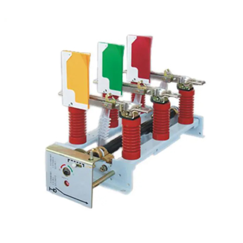
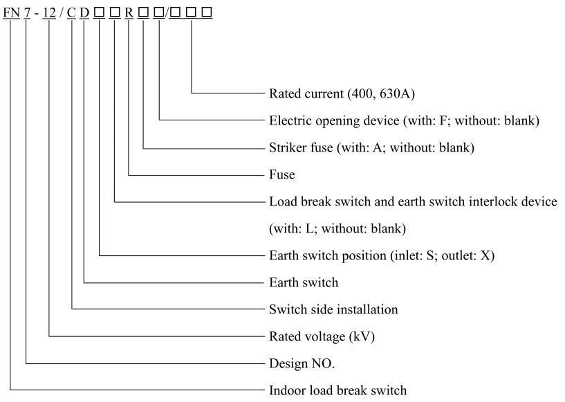
FN7-12 Series Indoor High Voltage Air Load Break Switch

Application
FN7-12 is a new type of air indoor high-voltage load break switch. It is suitable for AC 50Hz, rated voltage 12kV three-phase AC power system, as the breaking load current and closing short-circuit current.
Type Description
Working Conditions
● Ambient temperature: -25 °C~ 40°C;
● Altitude: <1000m;
● Relative humidity: daily average <95%; Monthly average <90%;
● There shall be no corrosive, combustion and explosion gas or vapor on the site;
● No frequent violent vibration.
Technical Parameters
Main specifications Note: (-) without (A) with Table 1
|
Name |
Type |
Model |
DS |
DX |
L |
R |
RA |
F |
|
|
|
|
Earth switch at inlet |
Earth switch at outlet |
Interlock device |
Fuse |
Striker fuse |
Electric opening device |
|
Load break switch |
Without tripper |
FN7-12 |
- |
- |
- |
- |
- |
- |
|
FN7-12DSL |
A |
- |
A |
- |
- |
- |
||
|
FN7-12DXL |
- |
A |
A |
- |
- |
- |
||
|
FN7-12R |
- |
- |
- |
A |
- |
- |
||
|
FN7-12DSLR |
A |
- |
A |
A |
- |
- |
||
|
FN7-12DXLR |
- |
A |
A |
A |
- |
- |
||
|
With striking tripper |
FN7-12RA |
- |
- |
- |
- |
A |
- |
|
|
FN7-12RAF |
- |
- |
- |
- |
A |
A |
||
|
FN7-12DXLRA |
- |
A |
A |
- |
A |
- |
||
|
FN7-12DXLRAF |
- |
A |
A |
- |
A |
A |
Rated parameters Table 2
|
Rated voltage kV |
Max. voltage kV |
Rated current A |
1min power frequency withstand voltage kV |
4s thermal stability current(RMS) kA |
Dynamic stability current(peak) kA |
Short circuit making current kA |
Rated breaking current A |
Rated transferring current A |
|
12 |
12 |
400 |
42/48 |
12.5 |
31.5 |
31.5 |
400 |
1000 |
|
630 |
42/48 |
20 |
50 |
50 |
630 |
1000 |
Rated parameters of fUse Table 3
|
Model |
Rated voltage kV |
Rated current A |
Rated current of fuse |
|
SDLA*J |
12 |
40 |
6,3,10,16,20,25,31.5,40 |
|
SFLA*J |
12 |
100 |
50,63,71,80,100 |
|
SKLA*J |
12 |
125 |
125 |
A*: with striker.
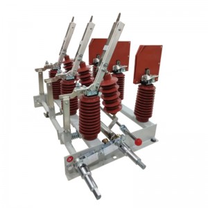
General Structure Drawing and Installation Size ( unit mm )
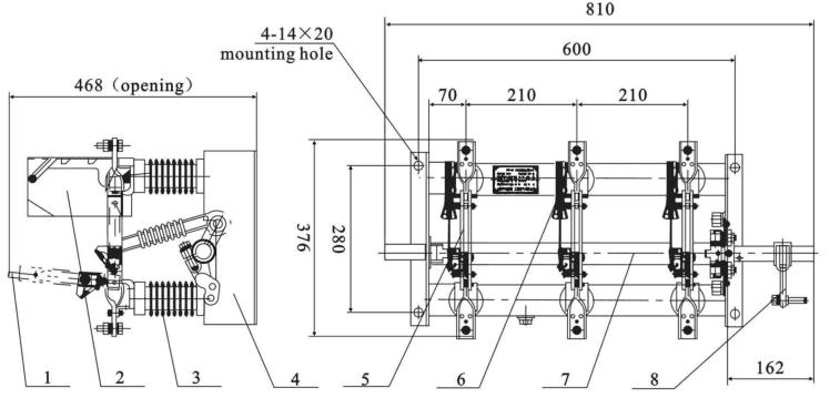
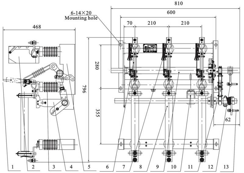
1. Arc Extinguishing Knife 2. Arc Contact Part and Arc Extinguishing Chamber 3. Insulator 4. Base
5. Dynamic Contact Knife 6. Static Contact Knife 7. Spring energy storage device (inside the main axis sleeve) 8. Main knife turning arm
Drawing 1 FN7-12 load switch outline and installation size
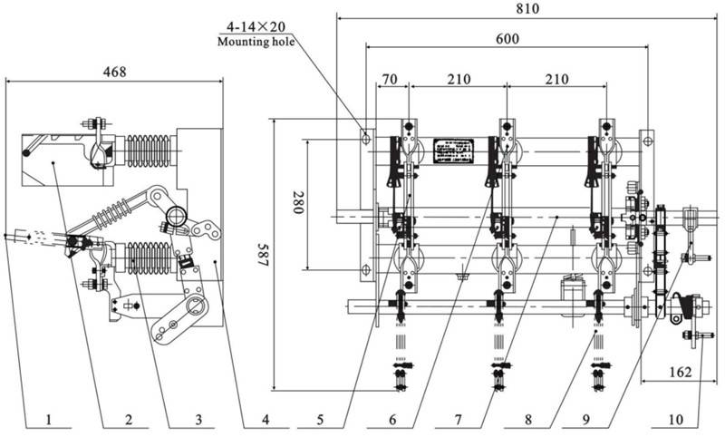
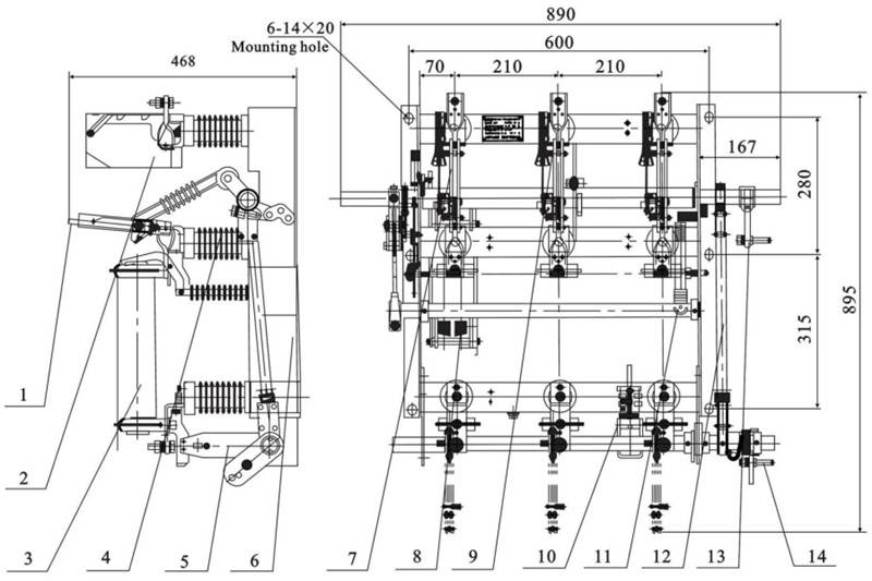
1.Arc Extinguishing Knife 2.Arc Contact Part and Arc Extinguishing Chamber 3. Insulator 4. Base
5. Dynamic Contact Knife 6. Static Contact Knife 7. Spring energy storage device (inside the main axis sleeve)
8. Earthing Knife 9. Main knife closing turning arm 10. Earthing knife closing turning arm
Drawing 2 FN7-12DXL load switch outline and installation size
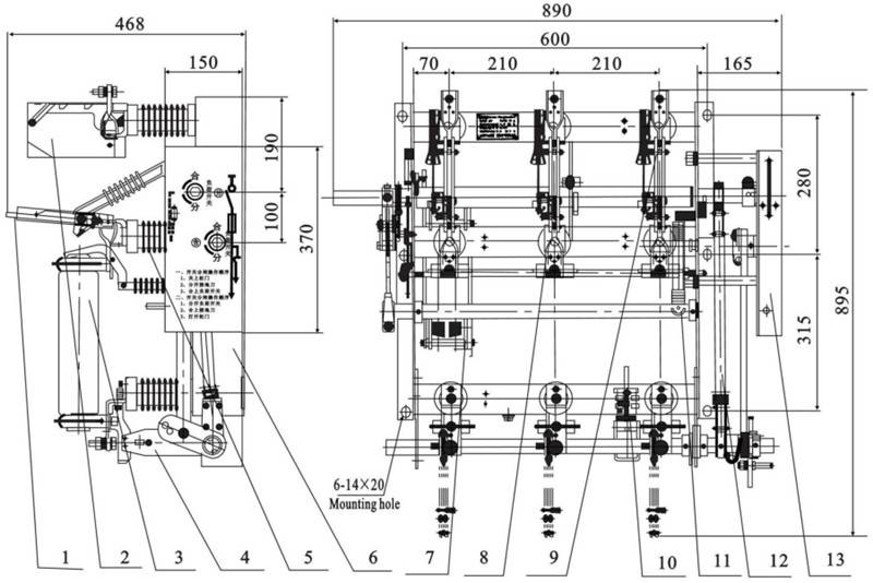
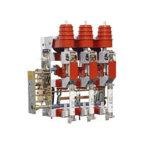
1.Arc Extinguishing Knife 2.Arc Contact Part and Arc Extinguishing Chamber 3. Insulator 4. Earthing knife
5. Base 6. Dynamic Contact Knife 7* Static Contact Knife 8. Fuse 9* Spring energy storage device (inside the main axis sleeve)
10. Earthing energy-storage spring 11. Interlock device 12. Main knife closing&opeing turning arm
13. Earthing knife closing&opening turning arm
Drawing 3 FN7-12DXLR separated type load switch outline and installation size

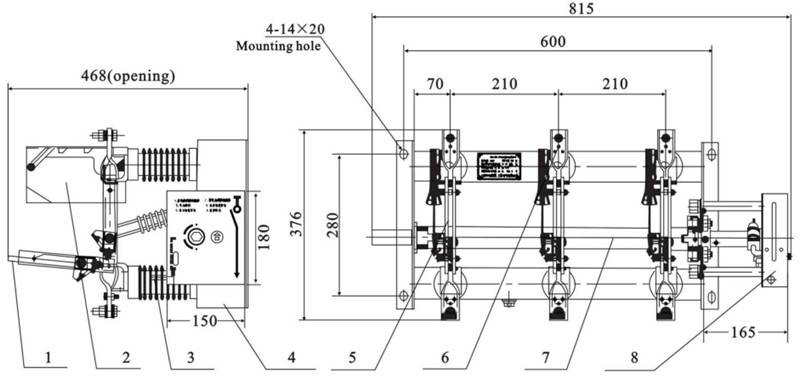
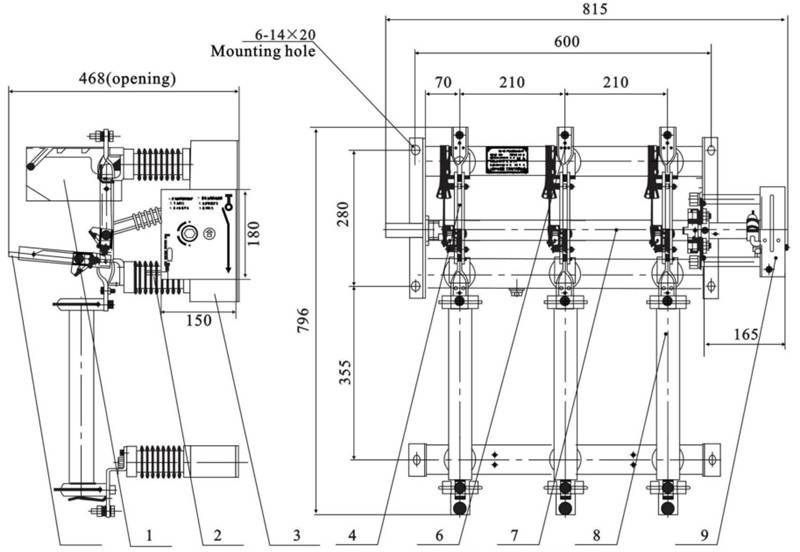
1.Arc Extinguishing Knife 2.Arc Contact Part and Arc Extinguishing Chamber 3. Insulator 4. Base
5. Dynamic Contact Knife 6. Static Contact Knife 7. Spring energy storage device (inside the main axis sleeve)
8. Fuse 9. Main knife closing&opening turning arm
Drawing 4 FN7-12R separated type load switch outline and installation size
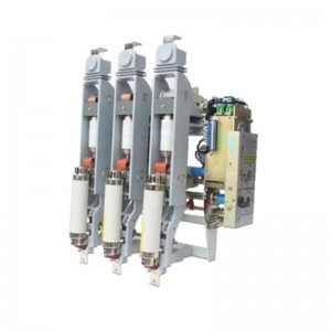
1 .Arc Extinguishing Knife 2.Arc Contact Part and Arc Extinguishing Chamber 3. Impact type Fuse 4. Insulator Base 5. Earthing knife
6. Base 7. Dynamic Contact Knife 8. Main knife closing spring 9. Static Contact Knife 10. Earthing energy-storage spring
11. Main knife opening spring 12. Interlock device 13. Main knife closing&opeing turning arm m 14.Earthing knife closing&opening turning arm
Drawing 5 FN7-12DXLRA integrated type load switch outline and installation size
1.Arc Extinguishing Knife 2. Arc Contact Part and Arc Extinguishing Chamber
3. Insulator 4. Base 5. Dynamic Contact Knife 6. Static Contact Knife
7. Spring energy storage device (inside the main axis sleeve) 8. Plate
Drawing 6 FN7-12C load switch outline and installation size
1.Arc Extinguishing Knife 2. Arc Contact Part and Arc Extinguishing Chamber
3. Insulator 4. Base 5. Dynamic Contact Knife 6. Static Contact Knife
7. Spring energy storage device (inside the main axis sleeve) 8. Fuse 9. Plate
Drawing 7 FN7-12CR separated type load switch outline and installation size
1.Arc Extinguishing Knife 2. Arc Contact Part and Arc Extinguishing Chamber 3. Impact type fuse 4. Earthling knife
5. Insulator 6. Base 7. Main knife closing spring 8. Dynamic Contact Knife 9. Static Contact Knife
10.Earthing energy storage spring 11. Main knife opening spring 12.Plate 13. Drawing 11
Drawing 8 FN7-12CDXLRA integrated type load switch outline and installation size
Products categories
-
FN12-12 Series Indoor High Voltage Air Load Bre...
-
FN5-12 Series Indoor High Voltage Air Load Brea...
-
FN7-12 Series Indoor High Voltage Air Load Brea...
-
FN7-24 INDOOR HV LOAD BREAK SWITCH
-
FZN25-12 Series Indoor High Voltage Vacuum Load...
-
FZRN61 Load Break Switch With Disconnect Switch...