
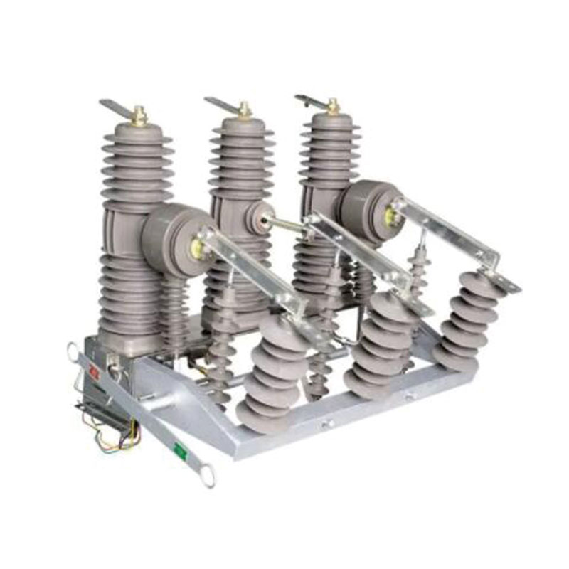
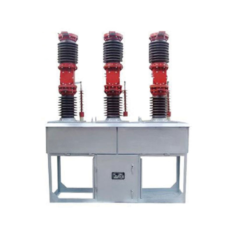
ZW32-24 outdoor HV vacuum circuit breaker is a 3-phase AC 50Hz 24kV outdoor switch equipment
Description
♦ Installation way: pole mounted;
♦ Operating mechanism: spring operating mechanism and permanent magnetic operating mechanism;
♦ Pole type: integrated pole;
♦ Application: outdoor 24kV substation, power plant.
♦ Operation type, manual, electric, remote control.
Product Standards
♦ IEC62271-100 High Voltage Switchgear and Controlgear Part 100: AC Circuit-breakers
♦ GB1984 High Voltage AC Circuit-breakers
♦ GB/T11022 Common Specifications for High-voltage Switchgear and Controlgear
Standards
♦ JB/T 3855 High Voltage AC Vacuum Circuit-breakers
♦ DL/T402 Specification of High-voltage AC Circuit-breakers
Environmental Conditions
♦ Ambient temperature: -35°C 〜+40°C;
♦ Altitude: <2000m;
♦ Wind speed < 35m/s;
♦ Earthquake intensity: <8 level;
♦ Filthy level: IV;
♦ Installation places: No fire, explosion hazard or serious filthy.
Main Technical Parameters
|
No |
Item |
Unit |
Value |
|
1 |
Rated voltage |
kV |
24 |
|
2 |
Rated current |
A |
630/1250 |
|
3 |
Rated frequency |
Hz |
50 |
|
4 |
Rated thermal current |
kA |
20/25 |
|
5 |
Rated short circuit breaking current |
kA |
20/25 |
|
6 |
Rated dynamic current (peak) |
kA |
50/63 |
|
7 |
Rated short-circuit closing current (peak) |
kA |
50/63 |
|
8 |
Thermal stability time |
s |
4 |
|
9 |
Rated operating sequence |
Times |
O-0.3S-CO-1 80S-CO |
|
10 |
1 min power frequency withstand voltage (inter-phase, earth/fracture) |
kV |
65 |
|
Lightning impulse withstand voltage (peak) (inter-phase, earth/fracture) |
125 |
||
|
Secondary circuit 1min power frequency withstand voltage |
2 |
|
No |
Item |
Unit |
Value |
|
11 |
Mechanical life |
Times |
10000 |
|
12 |
Rated short-circuit breaking current breaking times |
Times |
30 |
|
13 |
Rated circuit breaking times |
Times |
10000 |
|
14 |
Contact distance |
mm |
12±1 |
|
15 |
Over travel |
mm |
3±1 |
|
16 |
Inter-phase center distance |
mm |
380±1.5 |
|
17 |
Three phase closing and opening asynchronism |
ms |
≤2 |
|
18 |
Contact closing bounce duration |
ms |
≤2 |
|
19 |
Closing time |
ms |
25 〜80 |
|
20 |
Opening time |
ms |
23 〜50 |
|
21 |
Average opening speed |
m/s |
1.1-1.7 |
|
22 |
Average closing speed |
m/s |
0.5-0.9 |
|
23 |
Main conductive circuit resistance |
μΩ |
≤80 |
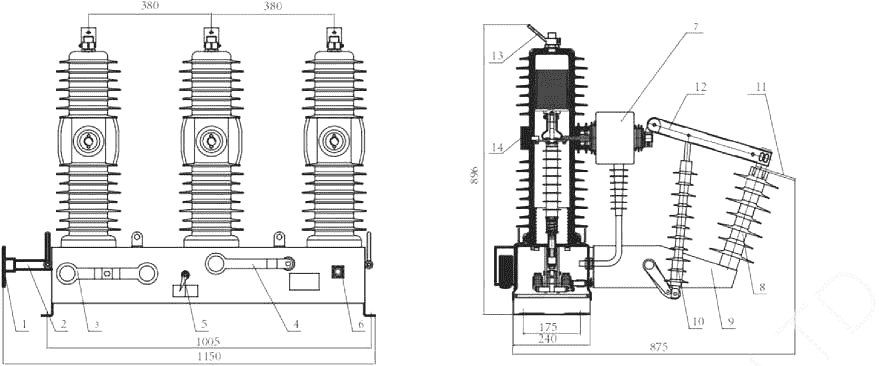
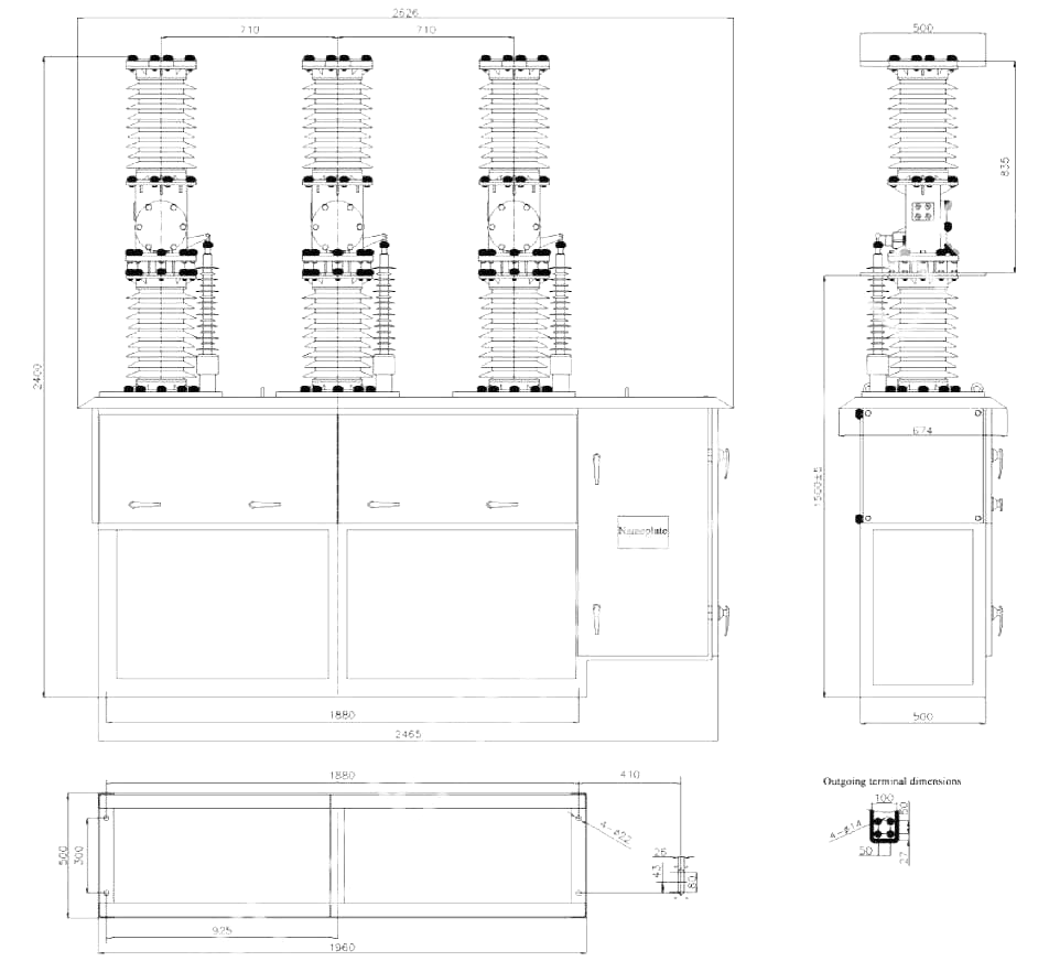
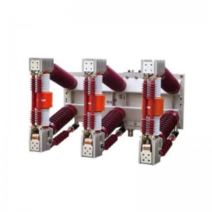
General Structure Drawing and Installation Size (unit: mm)

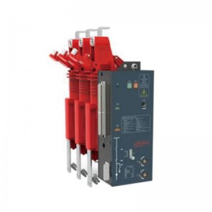
1. Upper outgoing line terminal
2. Interrupter
3. Insulating tube
4. Lower outgoing line terminal
5. Conductive clip
6. Flexible connection
7. Insulating lever
8. Contact pressure spring
9. Opening spring
10. Drive
11. Mechanism outgoing shaft
12. Operating mechanism
13. Mechanism box
14. Current transformer link board
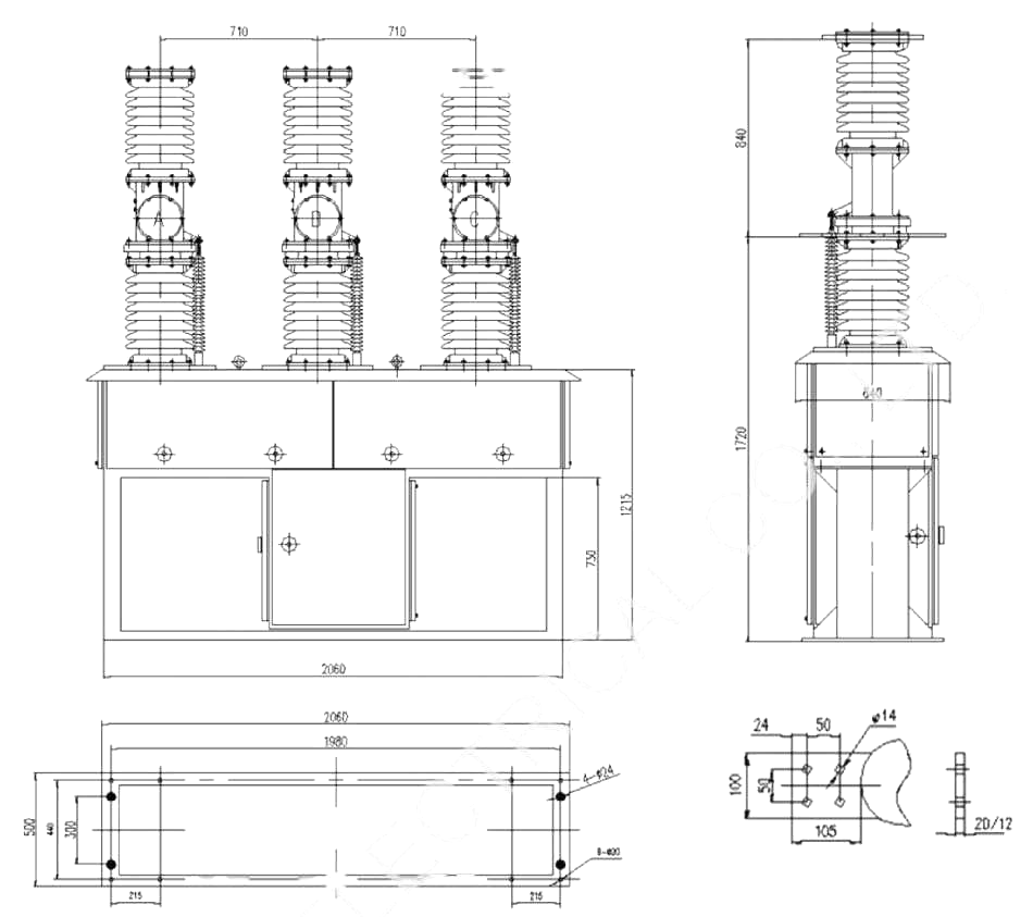
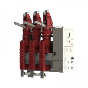
1. Operating handle
2. Disconnect main shaft
3. Circuit breaker manual opening/closing handle
4. Energy storage handle
5. Opening/closing indication
6. Wiring plug
7. Current transformer
8. Insulator
9. Insulating frame
10. Insulating lever
11. Incoming line terminal
12. Disconnect blade
13. Outgoing line terminal
14. Circuit breaker
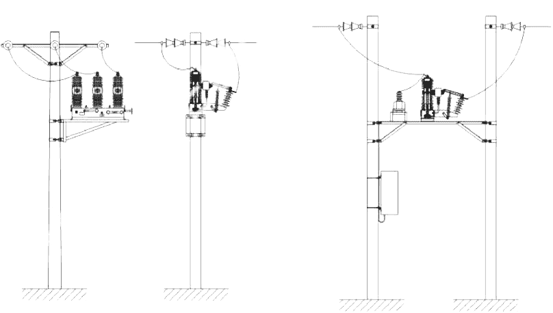
Installation ways (single pole/double pole)
Product Standards
♦ IEC62271-100 High Voltage Switchgear and Controlgear Part 100: AC Circuit-breakers
♦ GB1984 High Voltage AC Circuit-breakers
♦ GB/T11022 Common Specifications for High-voltage Switchgear and Controlgear Standards
♦ JB/T 3855 High Voltage AC Vacuum Circuit-breakers
♦ DL/T402 Specification of High-voltage AC Circuit-breakers
Environmental Conditions
♦ Ambient temperature: -40°C~+40°C;
♦ Altitude: <1000m;
♦ Maximum wind speed is 10km/h, minimum wind speed for the rated level (132/230kv) is 3.2km/h;
♦ Earthquake intensity: <8 level;
♦ Minimum nominal creepage distance: 31mm/kV;
♦ Air pollution degree: Class IV.
Main Technical Parameters
|
No |
Item |
Unit |
Value |
|
|
1 |
Rated voltage |
kV |
40.5 |
|
|
e |
Ratedinsulationlevel |
1 min power frequencyDry test (fracture, inter-phase, to earth)Wet test (to earth, external insulation) |
kV |
95 85 |
|
Lightning impulse withstand voltage(peak) |
185 |
|||
|
3 |
Rated current |
A |
1250, 1600, 2000, 2500 |
|
|
4 |
Rated short circuit breaking current |
kA |
20, 25, 31.5 |
|
|
No |
Item |
Unit |
Value |
|
5 |
Rated short circuit making current (peak) |
kA |
50, 63, 80 |
|
6 |
Rated peak withstand current |
kA |
50, 63, 80 |
|
7 |
Rated short time withstand current |
kA |
20, 25, 31.5 |
|
8 |
Rated operating sequence |
|
O-0.3S-CO-180S-CO |
|
9 |
Rated short circuit breaking current breaking number |
times |
20 |
|
10 |
Rated short circuit duration |
s |
4 |
|
11 |
Breaking time |
s |
≤0.09 |
|
12 |
Mechanical life |
times |
10000 |
|
13 |
Newly manufactured vacuum interrupter |
Ps |
≤1.33×10⁻³ |
|
Vacuum interrupter during 20-year storage time |
<6.6×10⁻² |
||
|
14 |
Circuit breaker net weight |
kg |
800 |
|
15 |
Clearance between open contacts |
mm |
22±2 |
|
16 |
Contact travel |
mm |
4±1 |
|
17 |
Average opening speed |
m/s |
1.4-1.7 |
|
18 |
Average closing speed |
m/s |
0.4-0.7 |
|
19 |
Contact closing bounce time |
ms |
≤3 |
|
20 |
Inter-phase opening and closing synchronism |
ms |
≤2 |
|
21 |
Closing time |
ms |
50≤t≤200 |
|
22 |
Opening time |
ms |
30≤t≤60 |
|
23 |
Each phase main circuit DC resistance (not includeCT internal resistance) |
μΩ |
≤100 |
|
24 |
Dynamic and fixed contact cumulative thickness allowed to wear |
mm |
3 |
|
25 |
Rated contact pressure |
N |
2500±200 |
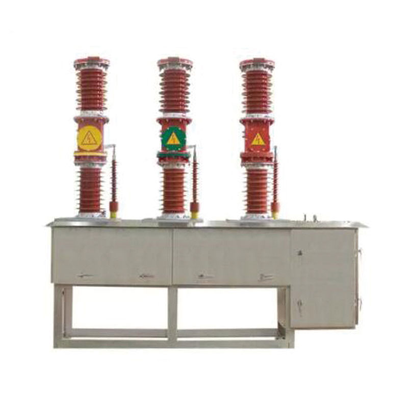
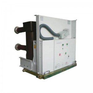
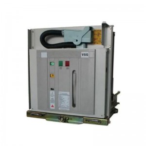
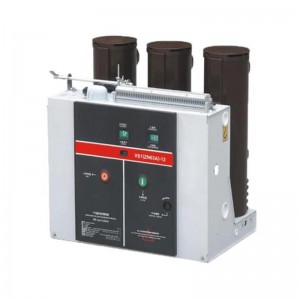
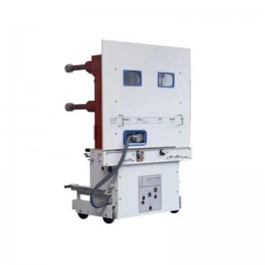
General Structure Drawing and Installation Size (unit: mm)
♦ Side-mechanism type
♦ Mid-mechanism type
Products categories
-
FZN25-12 Series Indoor High Voltage Vacuum Load...
-
VEF-12GD Side Installation Type 3 Working Posit...
-
VHK9-12 TYPE INTEGRATED COMBINED VACUUM CIRCUIT...
-
VS1-24 Series Indoor High Voltage Vacuum Circui...
-
VSG-12 Series Indoor High Voltage Vacuum Circui...
-

VSG-24 Series Indoor High Voltage Vacuum Circui...
-
VSG-24 Series Indoor High Voltage Vacuum Circui...
-
ZN12-12/40.5 Series Indoor High Voltage Vacuum ...
-
ZN63A-12 indoor high voltage vacuum circuit bre...
-
ZN85-40.5 Series Indoor High Voltage Vacuum Cir...