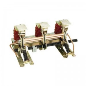
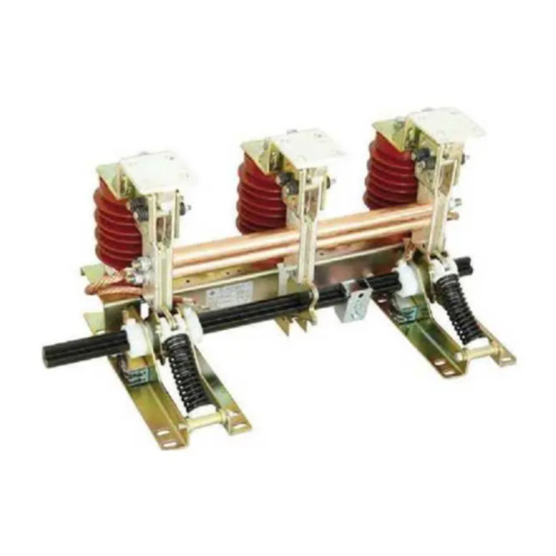
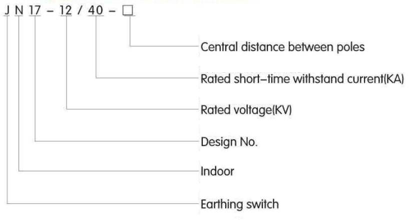
Jn17-12,40 Combined Grounding Switch
Product definition
Introduction
JN17-12/40 (old type is JN15-12/40) series indoor high voltage earthing switch is a new design and improved product of us according to the ESI type, the structure is assembled, suitable with electric power system with 3-10KV, Three-phase,AC 501601Hz, support with various kinds of HV switchgear and earthing protection. It is complied with GB1985-2004 and IEC129 standard.
Working condition
1. Ambient temperature:-10°C 一+40°C
2. Allitude:1000m Isensor heighi:140mm)
3. Relative humidity: Day average relative humidity w 95% Month average relative humidity w <90%
4. Earthquake intensity: w 8degree
5. Dirtiness degree: II
Mainly technical parameters
|
Item |
Unit |
Data |
|
|
|
Rated voltage |
KV |
12 |
|
|
Rated short time withstand current (thermal stability) |
KA |
40 |
|
|
Rated short circuit withstand time |
S |
4 |
|
|
Rated short circuit making current |
KA |
100 |
|
|
Rated peak withstand current (dynamic stability) |
KA |
100 |
|
Rated insulation leve |
Rated short time power frequency withstand voltage |
KV |
42 |
|
Rated lightning impulse withstand voltage |
75 |
||
|
|
Machinery Life |
time |
2000 |
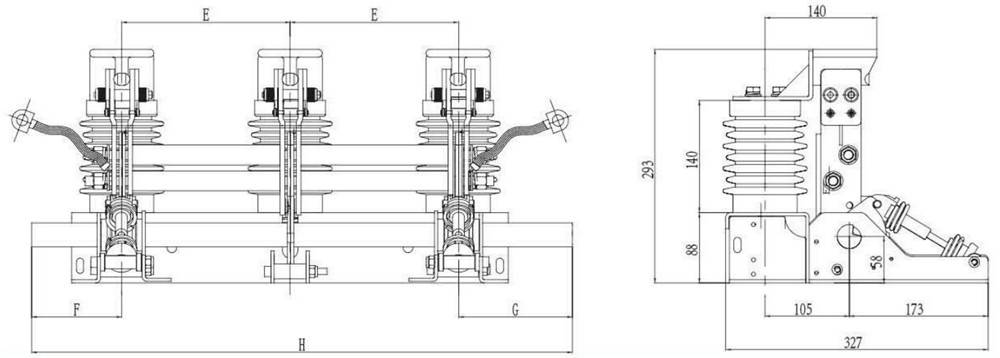
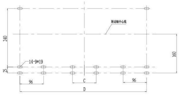
JN17-12/40earthing switch(ES-10/31.5) Outline and installation dimension
Copper terminal block
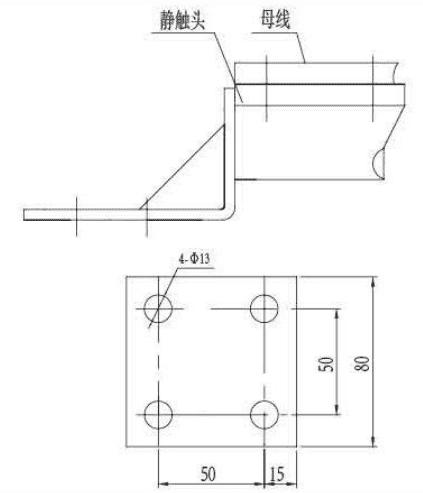
Hole location diagram
|
Specification |
E |
F |
G |
H |
D |
|
JN17-12/40-210 |
210 |
50 |
185 |
655 |
516 |
|
JN17-12/40-220 |
220 |
50 |
185 |
675 |
536 |
|
JN17-12/40-230 |
230 |
50 |
85 |
695 |
556 |
|
JN17-12/40-250 |
250 |
50 |
185 |
735 |
596 |
|
JN17-12/40-275 |
275 |
50 |
210 |
810 |
646 |
Order notesdndicate product specification, central distance between poles, if the electric display deviceltype ot me displaylneeded or not Please note the soft link length when ordering (normal L=250mm).