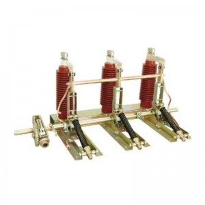
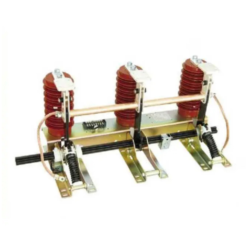
Jn15-24/31.5 Series Earthing Switch
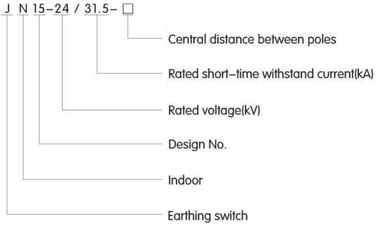
Product definition
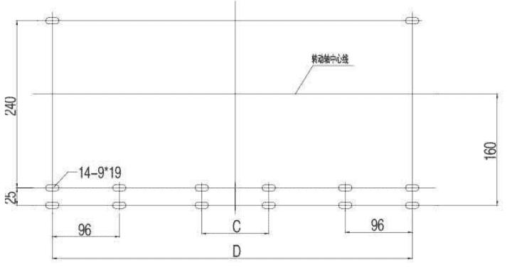
Installation drawing and hole location diagram
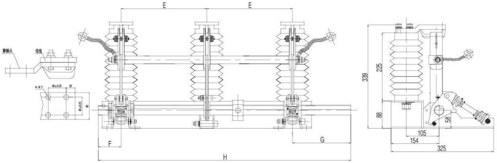
Hole location diagram
|
Product model |
E |
F |
G |
H |
D |
C |
|
JN15-24/31.5-210 |
210 |
75 |
160 |
655 |
516 |
|
|
JN15-24/31.5-22O |
220 |
75 |
160 |
735 |
536 |
|
|
JN15-24/31.5-23O |
230 |
75 |
160 |
810 |
556 |
96 |
|
JN15-24/31.5-25O |
250 |
75 |
160 |
810 |
596 |
96 |
|
JN15-24/31.5-275 |
275 |
75 |
185 |
810 |
646 |
96 |
Introduction
JN15-24/31.5 series indoor earthing switch is a new design and improved on the Jnl5 typejthe installing size without any changeLsuitable with electric power system with 20-24KVJhree-phase, AC 50(60)Hz, support with various kinds of HV switchgear and as earthing protection. It is complied with GB1985-2004 and IEC129 standard.
Working condition
1. Ambient temperature: -10X ~ +40°C ;
2.Altitude: W 1000m
3.Relative humidity: Day average relative humidity w 95%;
Month average relative humidity w 90沧
4.Earthquake intensity: w 8degree;
5. Class of pollution: II
Mainly technical parameters
|
Item |
Unit |
Data |
|
|
|
Rated voltage |
KV |
24 |
|
|
Rated short time withstand current (thermal stability) |
KA |
31.5 |
|
|
Rated short circuit withstand time |
S |
4 |
|
|
Rated short circuit making current |
KA |
80 |
|
|
Rated peak withstand current (dynamic stability) |
KA |
80 |
|
Rated insulation leve |
Rated short time power frequency withstand voltage |
KV |
65 |
|
Rated lightning impulse withstand voltage |
95 |
||
|
|
Mechanism Life |
time |
2000 |