GW4-40.5kv Outdoor Disconnector

Product Overview
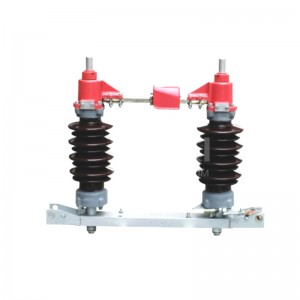
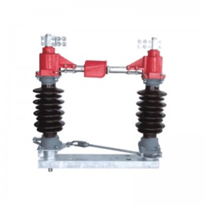
GW4-40.5 (D)kv outdoor Disconnector(high voltage isolation switch) is a three-phase AC 50HZ outdoor high voltage switch equipment, for open or close circuit when high voltage have voltage and no load, suitable for substation out line isolation switch.
The following technical standards for this type of product:
GB1985 - 89 "AC high voltage isolation switch and grounding switch”
GB/T11022 - 1999 common technical requirements for high voltage switchgear and control equipment standards
IEC129 (1984) "AC Outdoor Disconnector and grounding switch”
Model and meaning
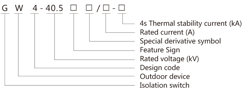
Feature Signs: D-ground switch, I II-ground switch type, G-improved product
Special Derivation Signs: W—Stain Resistant, GY—Plateau Type, H—High-cold Type, TA—Dry-Heat Type, TH—Damp-Heat Type
Normal operating conditions and installation conditions
a. Altitude: normal type ≤1000m, plateau type ≤4000m.
b. Covering water thickness <10mm
c. Wind pressure ≤ 700pa.
d. Seismic intensity is less than 8 degrees.
e. Ambient air temperature: upper limit +40°C, lower limit -30°C.
g. There is no flammable material, explosion hazard, chemical corrosion and severe vibration at the installation site.
Technical parameter
|
Model |
Rated voltage (valid) |
Rated current (A) |
Short-time withstand current |
Power frequency withstand voltage (valid) kV/60s |
Creepage distance cm/kV |
Terminal horizontal tension N |
Weight / 1P kg |
|||
|
Thermal current / 4s |
Dynamic current |
Ground |
Fracture |
Common |
Stain resistance |
|||||
|
GW4-40.5D |
40.5kV |
630 |
20kA |
50kA |
80 |
90 |
1.7 |
2.5 |
500 |
80 |
|
1250 |
31.5kA |
80kA |
||||||||
|
2000 |
31.5kA |
80kA |
100 |
|||||||
|
3150 |
40kA |
100kA |
||||||||
Main structure
The Outdoor Disconnector is a single pole double column horizontal rotating structure. The three poles can be used in groups, or the single pole for use. The isolation switch is composed of a chassis, a bearing seat, a post insulator, a conductive main circuit, and a mechanical connecting rod. The three pole joint, linkage pull rod, pipe joint, shaft pin, steel tube (user self), and manual operating mechanism (hereinafter referred to as operating mechanism) are connected in groups.
The grounding switch can be installed at one end or two ends of the isolator. The grounding switch at both ends of the isolation switch is controlled by the interlocking of the hand actuating mechanism, so that the isolation switch and the grounding switch are operated in the order of the main - ground - to - ground - in the main.
1. The underframe is made up of GB9787-88 hot rolled angle steel. The bearing seat is installed at both ends of the chassis, and 2 tapered roller bearings are installed to ensure that the shaft assembly is flexible.
2. Pillar insulators: there are three kinds of common type, anti pollution type and plateau type. Their performance meets the GB8287.1 "high pressure pillar porcelain insulator technical condition", GB8287.2 - 87 "high pressure pillar bottle insulator size and characteristic". The anti fouling type also meets the GB127744 - 91 "stain resistant outdoor rod type post insulator". Each pole isolation switch is equipped with two post insulators, the post insulator is erected on the shaft assembly, and the upper end is fixed with a conductive main circuit.
3. The main circuit of the conduction is made up of the connection block and the assembly of the left and right contacts. The structure of 630A and 3150A is basically the same, only the number of conductive tube cross section, the surface coating, the number of contact fingers and the difference between the soft conductors. The wiring block is equipped with a guide rod and a flexible conductor. It has less resistance and better electrical conductivity than traditional rolling contact method, as shown in Figure 3. The construction of the right and left contact assembly and the contact state after closing are shown in Figure 4.
4. Ground switch: the grounding switch is installed at the end of the isolator underframe, and the static contact of the earthing switch is installed on the conductive pipe of the main conduction circuit.
5. Mechanical connecting rod: the isolating switch is operated by the operating mechanism by the operating mechanism installed in the middle of the bottom frame, and through the spindle rod to drive the left touch side insulator to rotate 90 degrees. The linkage pull rod drives the three pole disconnecting switch to switch on and off. The ground switch is driven by the driving shaft to drive the ground knife, and the ground knife is rotated upward (downward) for a certain angle to complete the closing (sluice). The pole of each pole of the three pole earth switch is connected by a 32 * 3 steel pipe to achieve three pole linkage. The three pole disconnector is connected with the 25 * 2.5 steel pipe connection to realize three pole linkage. The three pole disconnecting switch is connected with a 25 * 2.5 steel pipe to realize three pole linkage. The isolating switch is connected with the operating mechanism with a diameter of 42 * 3 steel pipe, and the steel pipe user is provided by himself.
6. Actuating mechanism: the isolating switch is equipped with CS17 manual operating mechanism when leaving factory. The mechanism is composed of a base, an interlocking plate, a handle and an auxiliary switch. The auxiliary switch has 4 poles and 8 poles two specifications, 2 pairs and 4 pairs of normally open normally closed contacts respectively. The use of interlocking and transmitting signals. After the electromagnetic actuator is installed with the manual operation mechanism, the isolating switch can increase the electric locking function. The electromagnetic lock and its installation accessories are separately priced and supplied, and installed by the users themselves.
Installation and debugging
1. Pre-installation check
a. Check whether the number of isolation switches, parts and accessories is in line with packing list.
b. The product nameplate data is consistent with the order.
c. Whether the product is damaged, and whether the pillar insulator has cracks.
d. Whether the rotation of each rotating part is flexible or not.
e. Whether the operating mechanism is flexible, whether the position of closing and opening is correct, and whether the auxiliary switch is normal.
2. Outdoor Disconnector can only be installed horizontally. Place the Outdoor Disconnector on the mounting bracket at the same horizontal height first, and then correct the distance between the poles to make the chassis parallel to each other. Correct the three-pole Outdoor Disconnector two-column insulator core axis, earth switch the axis line of the shaft, connect the switch after the Outdoor Disconnector is fixed.
3. When the isolation switch is closed, the left and right contacts shall be on the same horizontal line, the upper and lower sides offset by <5mm, and the left and right contact assembly contact positions shall be centered in the centerline of the two pillar insulators, and the right contact shall be embedded in the left The contacts on the contact side are in contact with each other, and the gap between the contact on the left contact side and the positioning plate is ≤2mm. When necessary, the length of the monopole pull rod can be adjusted; and it is allowed to increase or decrease the adjustment spacer at the top and bottom of the pillar insulator, but each pad thickness <3mm.
4. Adjust the length of linkage rod, so that the three-phase isolation switch closing error <5mm. Then adjust the length of the main shaft pull rod and the linkage pull rod respectively, so that the opening angle of the isolation switch after opening is 90°.
5. Adjust the arm angle of the grounding switch and the effective length of the connecting rod so that the grounding switch is synchronized with the operating mechanism when the opening and closing. The grounding switch is horizontal when in the opening position.
6. The installation position of the manual operation mechanism is shown in Fig. 1 and Fig. 2. After assembling the mechanism and the platey, insert A10×50 conical pin and fasten the two M10 bolts. Double grounding isolation switch, from the bottom of the chassis to operate the shaft axis downward vertical line, single grounding and non-grounding from the lower end of the post insulator assembly to the vertical line, so that it coincides with the center of the operating mechanism shaft, and then the mechanism is installed and fixed. The double grounding Outdoor Disconnector sets the shaft on the actuating shaft. The single grounding and non-grounding isolation switch sets the shaft on the actuating shaft and shaft assembly, measures the effective size, and prepares a φ42×3 seamless steel pipe. The two ends of the steel pipe are respectively welded to the bushing and the plate assembly.
7. Remove dirt from the rotating parts and electrical contacts of the machines and re-inject grease.
8. Measuring the resistance value of the main circuit of the disconnector should comply with the regulation in the table.
9. Manual operation 3~5 times, stable operation, opening-closing position of Outdoor Disconnector and grounding switch is correct, good contact.
10. After installation, it can be run after inspection confirms that it meets the requirements.
|
Rated voltage kV (valid) |
Rated current A |
Resistance value of main circuit μΩ |
Remarks |
|
40.5 |
630 |
≤180 |
1. Does not include wiring clips 2. Reference value. |
|
1250 |
≤100 |
||
|
2000 |
≤65 |
||
|
3150 |
≤36 |
Operation and maintenance
1. Outdoor Disconnector must be operated after the circuit load is cut off. Outdoor Disconnector should be repaired once a year after the operation, if there is a serious short-circuit fault, it should be repaired immediately after failure.
2. Remove the dirt on the electric contact surface and the post insulator, and apply industrial vaseline to each electrical contact surface.
3, clean the oil pollution on the mechanical transmission parts and rotate parts, re-injected lubricating grease; painted parts repainted.
4. Replace the damaged parts. Check all fasteners and shaft pins in each area and tighten them if loose.
5. When necessary, test power frequency withstand voltage according to Table 1, measure the main circuit resistance according to Table 2, the main circuit resistance will increase after the isolation switch is running, but not more than 1.2 times of the values listed in Table.
Packing, transportation and storage
Packaging, transportation and storage
1. The isolating switch is generally a three-pole box package. When the user makes a special request, it is packaged as a unipolar package. The hand-operated mechanism and the accessory box of the accessories are packaged together with the product.
2. Transport products should follow the outside of the box marked by the operation, not allowed to turn and down.
3. After the product arrives at the station, please check it in time. If problems are found, please contact the manufacturer immediately for quick processing.
4. After the product is unpacked, if it cannot be installed immediately, store it in a dry and sheltered place for a long-term inventory, and make regular inspections.