An RCBO is a residual-current circuit breaker with overcurrent protection. The category combines two protection questions within one device:
Is current returning through the intended circuit path?
Is circuit current above the intended operating condition?
The exact detection thresholds, trip behaviour, pole arrangement and product ratings depend on the selected device and must be confirmed from its documentation.

A residual-current function evaluates whether current is returning through the intended circuit path. A qualifying imbalance may indicate current flowing through an unintended path.
This category-level explanation does not specify a threshold, waveform type or trip time for the photographed products.
An overcurrent function responds when circuit current exceeds the intended operating condition according to the selected device design. The cause may relate to overload or short-circuit conditions, but the exact response depends on product characteristics and system coordination.
The infographic does not state a universal curve or breaking capacity.
With the device closed and the circuit operating normally, current flows through the protected circuit to the load.
The RCBO category incorporates residual-current and overcurrent protection functions. The infographic presents this as a conceptual monitoring stage rather than a diagram of hidden internal components.
When an abnormal condition meets the selected device's operating criteria, the protection function initiates a response.
Exact thresholds and timing must come from the selected-product documentation.
The operating mechanism opens the protected circuit according to the device design and detected condition.
The infographic does not claim zero delay or a specific operating time.
An unexplained trip should not be treated as a routine switch-off event. Identify the cause, isolate safely and follow the approved inspection, reset and return-to-service procedure.
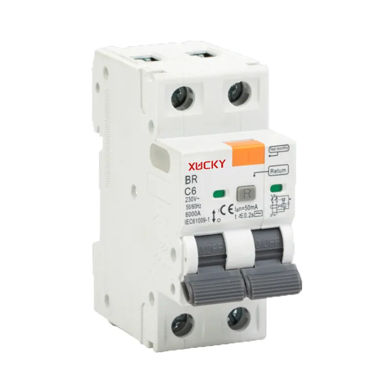
The real BR Series images visibly show:
l Test controls
l Operating handles
l Terminal openings
l Front labels and symbols
l Two-pole and four-pole formats
They do not reveal the complete internal detection or trip mechanism. No hidden structure has been reconstructed in the infographic.
l Use the visible test function only according to the exact product instructions and approved site procedure.
l A test-control operation does not replace:
l Verification of correct installation
l Circuit testing
l Protective-conductor and earthing checks
l Inspection of terminals and conductors
l Protection coordination
l Scheduled maintenance
l Work by qualified personnel
l Reset and Return-to-Service Review
l Whether the trip cause is known
l Whether the circuit and load can be safely inspected
l Whether conductors, terminals or equipment show abnormal conditions
l Whether moisture, insulation damage or an unintended current path may be present
l Whether the load may have created an overload or fault condition
l Whether the exact product instructions permit reset
l Whether qualified-personnel investigation is required
l Never repeatedly reset a device without identifying the cause of an unexplained trip.
l Selection Checklist
l Provide the following before product selection:
l System and circuit information
l Supply characteristics
l Load type and operating behaviour
l Required pole format
l Continuous load current
l Prospective fault information
l Required residual-current protection characteristics
l Required tripping characteristic
l Earthing arrangement
l Upstream and downstream protection
l Selectivity and coordination requirements
l Installation environment
l Exact documentation and testing requirements
An RCBO does not replace correct circuit design, conductor sizing, earthing, isolation, installation testing, protection coordination or maintenance.
Installation, testing and fault investigation must be performed by qualified personnel using the approved project design and exact product instructions.
Need an RCBO for a distribution or control project?
Send XUCKY your circuit, load, pole-format, residual-current and coordination requirements for product-document review.
Request the exact BR Series documentation before confirming ratings, wiring or installation details.At category level, an RCBO combines residual-current protection with overcurrent protection. Exact operating characteristics depend on the selected product.
No. It shows only real external product photographs and a conceptual protection sequence. Hidden internal components are not reconstructed.
The test function is used according to the exact product instructions to check device operation. It does not replace installation testing, circuit inspection or scheduled maintenance.
An unexplained trip should be investigated first. Identify the cause, isolate safely and follow the approved reset and return-to-service procedure.
No. All visible numbers and symbols apply only to the photographed units. Confirm the selected model's exact ratings from its approved documentation.
No. Correct earthing, conductor sizing, isolation, circuit design and protection coordination remain separate project requirements.
No. Pole format must match the circuit arrangement and project requirements. The images show two photographed configurations, not universal interchangeability.